 PA Trace for live sound
How to set up a dual-channel measurement rig
A transfer function is only as good as the two signals it compares. This guide covers the hardware, where to split off the reference, how to set the levels, which test signal to play, and a short checklist that tells you the rig is ready before the doors open.
Updated 17 November 2026
What you need
- A computer that runs the analyzer without audio dropouts. A laptop is the norm, because you will move it.
- An audio interface with at least two inputs: one for the measurement microphone, one for the reference. More inputs let you run several microphones at once. The measurement input needs a preamp with phantom power.
- A measurement microphone. Omnidirectional, with a flat response that changes little with the angle of the arriving sound. A vocal or instrument microphone is not a measurement microphone: its response and its pickup pattern are part of its sound.
- An acoustic calibrator (94 or 114 dB SPL), only if you want to read absolute levels: SPL logging, an RTA in dB SPL, speech intelligibility. A transfer function is a ratio of two inputs and does not need it.
- A long microphone cable or a wireless link, a stand, and a windscreen for outdoor work.
On Windows, use the interface maker's ASIO driver if there is one: it is the most stable. Windows Audio (WASAPI) also works. On a Mac, Core Audio is built in.
The signal flow
A dual-channel analyzer compares the signal the system is sent (the reference) with what the microphone hears (the measurement). Everything between those two points is what you measure. So the first decision is where the reference comes from.
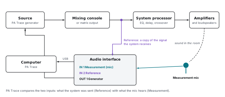
Where to take the reference
| Reference taken from | The measurement includes | Use it for |
|---|---|---|
| The console output that feeds the system processor (a matrix or spare output carrying the same signal) | Processor, amplifiers, loudspeakers, room | Tuning the system. The usual choice, and it works with any program, including the show. |
| The processor output that feeds one amplifier channel | Amplifier, loudspeaker, room | Checking a single box or way without the processor's own EQ and delay. |
| A loop-back of the interface's own generator output | Everything from the interface output on | Quick checks when the analyzer's generator drives the system directly. |
If the reference is taken before the console's own EQ, that EQ becomes part of the measurement. That is useful when you want to check the console EQ, and wrong when you want to tune the system behind it.
Many interfaces can offer their own outputs as inputs (a loop-back). That gives you a reference without a cable, but the loop-back is set in the interface's own mixer or control panel, not in the analyzer.
Levels
- Reference: RMS well above about −45 dBFS, peaks below −1 dBFS. A weak reference adds noise to every frequency of the result.
- Microphone: above about −60 dBFS RMS with the system playing, and never clipping at show level.
- Test signal: start the generator low and bring it up to a comfortable level well above the background noise. Full-scale noise through a large system can damage loudspeakers and hearing.
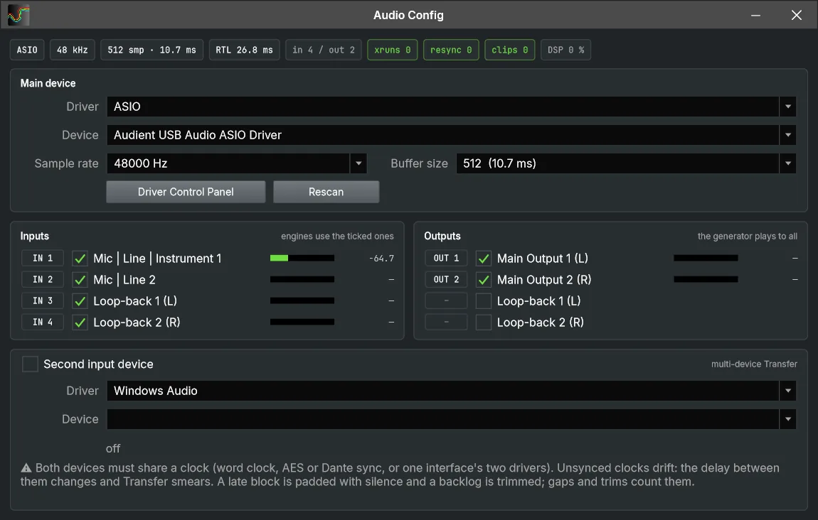
Sample rate and buffer size
48 kHz covers the audio band and is what most processors and audio networks run at. There is no measurement benefit in going higher. The buffer size only decides how much audio the driver hands over at a time: the analyzer measures and removes the delay between reference and microphone anyway, so latency does not change the result. Pick the size that runs without dropouts, and raise it if the dropout counter moves.
Two interfaces at once
Sometimes the reference comes over the network (Dante or AES into one device) and the microphone into a USB interface. That works only if both devices share a clock: word clock, AES or Dante sync. Clocks that are not locked drift apart, so the delay between reference and microphone keeps changing and the transfer function smears. PA Trace takes a second input device for this case and counts gaps and trims, which tell you when the clocks are not locked.
Which test signal
| Signal | Use |
|---|---|
| Pink noise | The standard for transfer function and RTA work: equal energy per octave, like music. |
| Periodic pink noise | Repeats exactly once per FFT, so one run gives a clean impulse response without averaging. |
| Band-limited pink | Measuring subwoofers alone (for example 25 to 125 Hz) so the tops get no energy. |
| Sine, log sweep | Rattles, distortion, checking one driver. |
| Program material | During a show, with the console output as reference: the music itself is the test signal. |
Where to put the microphone
Where it represents the audience the loudspeaker covers: at ear height, away from walls and large objects. For a main system, a good first position is on axis about two thirds of the way back in its coverage. Measure one system, or one part of it, at a time, with everything else muted. One position shows one seat, so plan to measure several before you decide on EQ (see how to EQ a PA system).
Checklist before the job
| Check | What you should see |
|---|---|
| Audio device | Right device and sample rate; no dropouts and no clips after a few minutes. |
| Reference | Its meter moves with the signal and stays below full scale. |
| Microphone | Its meter moves when you speak near the mic; nothing clips at show level. |
| Delay | The delay found matches the distance: about 2.9 ms per meter. |
| Coherence | High across the band with the system playing (in PA Trace, a green health dot). |
| Calibration | With the calibrator on the mic, the SPL meter reads the calibrator's level. |
In PA Trace: Config > Audio Config chooses the device and inputs; Add TF Engine pairs a microphone input with a reference input; Track finds the delay. Help > Verify Measurement Accuracy runs a known system through the analysis on your own computer and reports PASS or FAIL against the stated accuracy (0.20 dB and 1.0° rms on a clean signal), so you know the maths is right before you trust a trace.
Related guides
- Microphone calibration SPL calibration with a 94 dB calibrator, mic correction files, and when each one matters.
- Coherence explained What the coherence trace means, what each pattern of low coherence points to, and how to raise it.
- Transfer function measurement, explained Magnitude, phase, coherence and the impulse response: what they are and how to read them.
- Troubleshooting No signal, low coherence, a phase that will not settle, a delay that jumps: causes and checks, quickest first.